Difference Between Sheet Metal Design And Generative Sheet Metal Design
Catia Sheetmetal Bend Tables Explained Inceptra

Advanced Catia Sheetmetal Grabcad Tutorials

Generative Sheet Metal Design Catia I Assignment 1 I Part 1 Youtube

Solidworks Sheet Metal Tutorial Switch Box Youtube Sheet Metal Drawing Solidworks Tutorial Sheet Metal

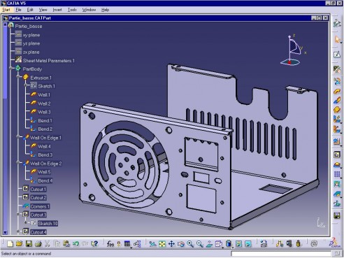
Catia V5 Mechanical Product Design

Catia V5 V6 Tutorial Sheet Metal Design Tutorial Part 02 Design Tutorials Metal Design Tutorial

But it does not inc.
Difference between sheet metal design and generative sheet metal design.

Catia V5 V6 Tutorial Sheet Metal Design And Manufacturing In Detail Sheet Metal Metal Design Metal

Solidworks 2013 Sheet Metal Metal Furniture Design Sheet Metal Drawing Solidworks

Catia V5 Tata Technologies Plm Solutions

Catia Sheet Metal Tutorial For Beginners Youtube
Catia V5 Training I Get It

Onshape Goes Metal Sheet Metal Solidsmack

Catia V5 Tutorial For Beginners 118 Sheet Metal Design 01 Window Regulator Mounting Bracket Youtube
What Is The Module In Catia How Many Modules In Catia And Their List Quora
About Y Factor And K Factor

Sheet Metal Tutorial Youtube

Pin On Solidworks

Solidworks Sheet Metal Lofted Bend Youtube Sheet Metal Drawing Solidworks Sheet Metal

Catia V5 Tutorial For Beginners 123 Sheet Metal Design 06 Mtg Bracket Youtube

Sheetmetal Designer Smw

Autodesk Inventor Sheet Metal Tutorial Basics Youtube Autodesk Inventor Metal Furniture Design Solidworks Tutorial

Solidworks Sheet Metal Exercise Youtube Sheet Metal Drawing Sheet Metal Solidworks

Nes Learning Youtube Em 2020 Contabilidade

Bend Relief In Sheet Metal In 2020 Design Guidelines Sheet Metal Metal Design
3

Designing With Sheet Metal In Onshape

Sheetmetalcone Png 734 576 Sheet Metal Fabrication Sheet Metal Work Sheet Metal

Recognizing Walls From An Existing Part

Solidworks Sheet Metal Tutorial Vent And Emboss Youtube Solidworks Sheet Metal Solidworks Tutorial
Solidworks Sheet Metal Forming Tool Exercise Youtube Solidworks Sheet Metal Solidworks Tutorial

Pin On 3d Cad Modeling Services

Angle Bracket Sheet Metal Drawing Sheet Metal Technical Drawing

76 Questions With Answers In Catia Science Topic

Catia V5 Tutorial For Beginners 128 Biw Design Sheet Metal Design 04 Bracket Youtube

Solidworks Tutorial Design Of Tank Youtube Solidworks Tutorial Mechanical Design Solidworks

3d Model Of A Sheet Metal Box And Cover Used To Enclosure Electrical Gear Model Created With The Help Of Sheet Metal Sheet Metal Fabrication Sheet Metal Work

Pin Em Solidworks

Thom Tremblay Founder Author Teacher Concepts And Design Linkedin
Displaying Bend Radius On Drawings In Catia V5 Rand 3d Insights From Within

Metal Origami Flat Pack Sheets Form Super Strong Shapes Sheet Metal Fabrication Metal Sheet Design Metal Fabrication

Fabrication Of Edges Joints Seams And Notches Sheet Metal Sheet Metal Work Sheet Metal Fabrication

Catia V6 Essentials Pdf In 2020 Metal Design Industrial Engineering Surface Design

Metal Origami Flat Pack Sheets Form Super Strong Shapes Sheet Metal Metal Sheet Design Metal Design

Ramakrishna Resume 3 2 Years Experience In Catia

Sheet Metal Stool Furniture Metal Sheet Design Sheet Metal Fabrication Metal Stool

How To Make A Sheet Metal Box Sheet Metal Metal Box Metal Tree Wall Art

Sheet Metal Tool Box Plans Quotes Metal Tool Box Sheet Metal Tools Tool Box

Sheet Metal Basics Mechanical Engineering Interview Questions Dimu S Tutorials Youtube

Pin On Stay

Homemade Sheet Metal Bender Sheet Metal Bender Metal Bender Sheet Metal Brake
Source : pinterest.com
