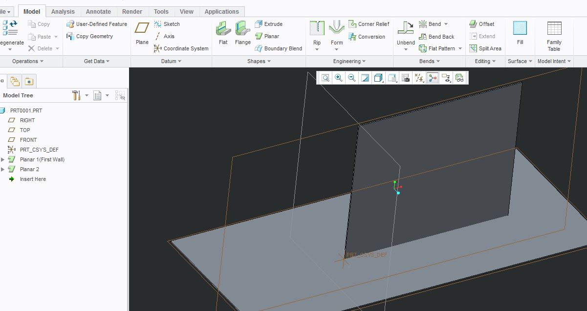
Creo Sheet Metal Planar Bent
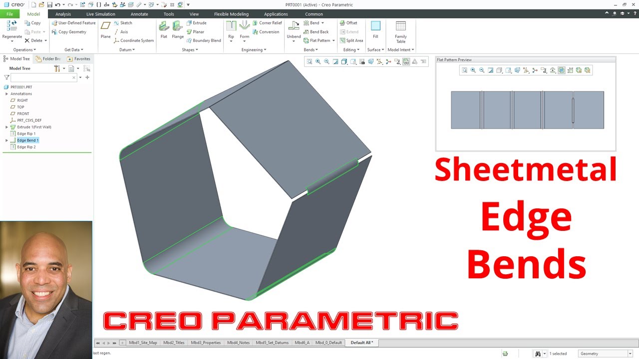
Creo Parametric Sheetmetal Edge Bends Youtube
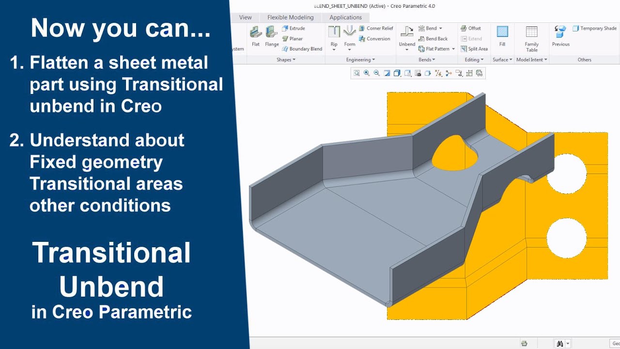
Creo Sheet Metal Transitional Unbend And Conditions In Creo Parametric Youtube

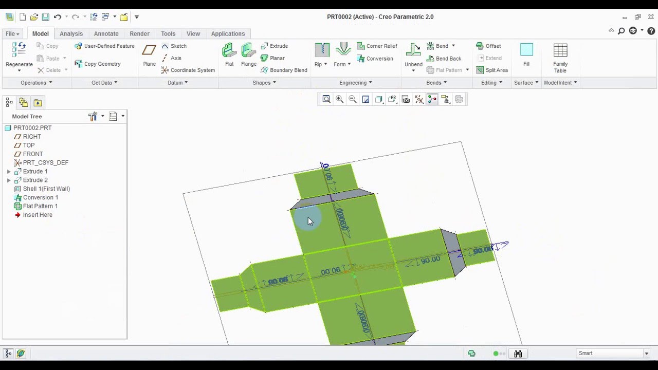
Sheet Metal Flat States

How To Convert A Solid To A Sheetmetal With Creo 4 Youtube
How To Use Join Command In Sheetmetal In Creo Grabcad Questions

Twist Command Sheet Metal Creo 2 0 Youtube

Figure sm 10 base feature blended wall flat sketch the boundaries of the wall fig.
Creo sheet metal planar bent.

Creo Parametric 5 0 Enhancements Sheet Metal Flat Reps Youtube

Unfolding Sheet Metal With Ptc Creo High Peak Systems Software Solutions For Design Professionals

Add Flat Pattern In Sheet Metal Drawings Creo Parametric 5 0 Youtube
Solid To Sheet Metal Conversion In Creo 2 0 Youtube

Sheet Metal Modeling And Drawing In Creo Youtube
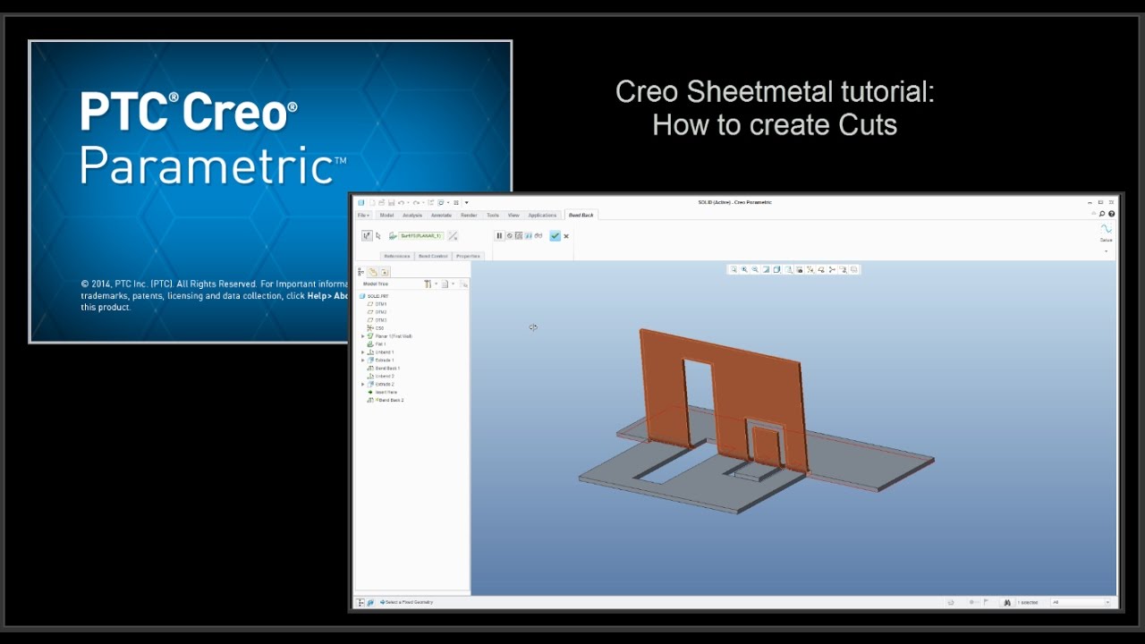
Creo Sheetmetal Tutorial How To Create Cuts Youtube

E17 Creo Parametric 2 0 Sheet Metal Basics Youtube

Solidworks Sheet Metal Lofted Bend Youtube Sheet Metal Drawing Solidworks Sheet Metal

Solidworks Sheet Metal Forming Tool Exercise Youtube Solidworks Sheet Metal Solidworks Tutorial

Bend Order In Solidworks Sheet Metal Parts Solidworks Sheet Metal Solid Works

Creo Parametric Sheetmetal Mode Flange Wall Youtube

Engine In Creo 3d Modeling Tutorial Parametric Mechanical Design

Sheet Metal Parts With Non Uniform Thickness Youtube

Siemens Nx Sheet Metal Design Youtube
Solidworks Tutorial Sheet Metal Drawings Youtube

Precise 2 Unfold Sheet Metal Model In Autocad Sample 3 Youtube
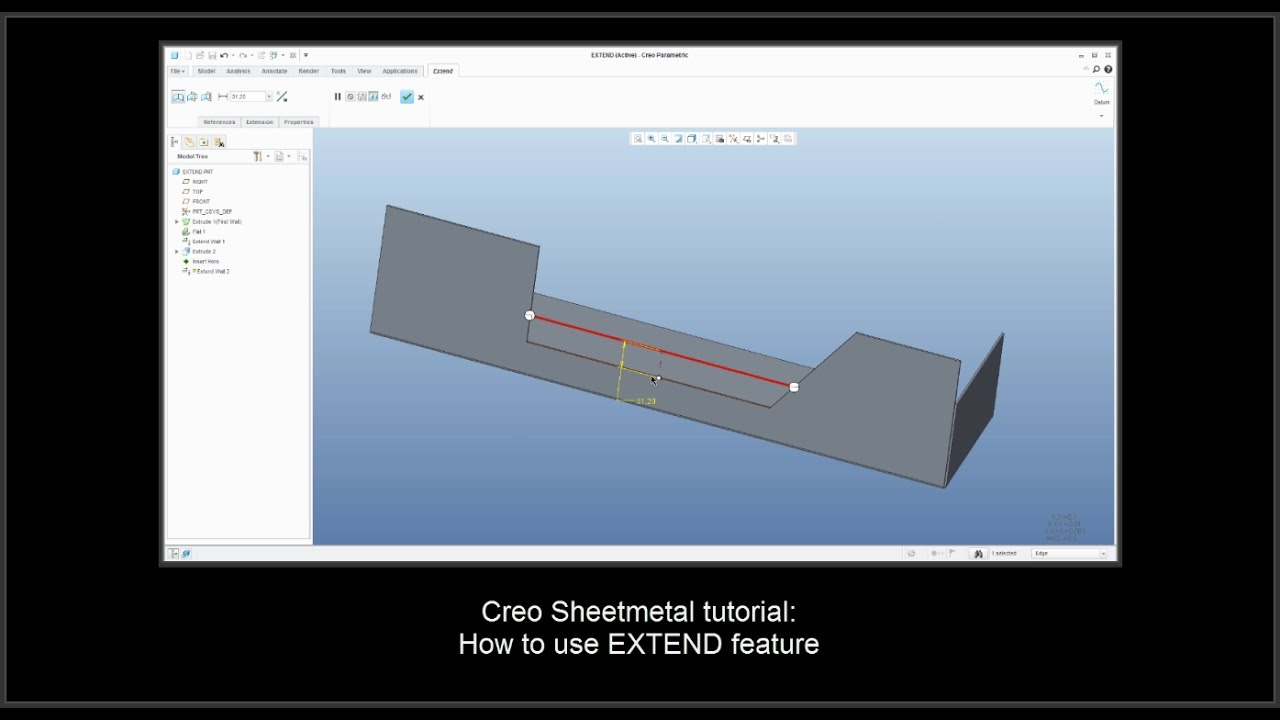
Creo Sheetmetal Tutorial How To Use Extend Feature Youtube

Solidworks Surface Tutorial Basics Of Solidworks Surface Solidworks Solidworks Tutorial Solid Works
Https Encrypted Tbn0 Gstatic Com Images Q Tbn 3aand9gct3zfazig75npdzpw Xd R1gzsyacdxiq4uba7vtl4pdytnncyc Usqp Cau
Allowance Tables And Formulas

Tutorial Sheet Metal Conversion Two Examples Ptc Community

Solidworks Tutorial Sheet Metal Forming Tool Youtube Solidworks Tutorial Solidworks Metal Forming

Autodesk Inventor Tutorial For Beginners Exercise 7 Youtube Autodesk Inventor Autodesk Inventor

Solidworks Sheet Metal Drawing Tutorial Bend Line Flat Pattern Unfolded Bend Table Punch Table Youtube

Splitting A Sheet Metal Part Into Multiple Bodies Youtube

Solidworks Sheet Metal Gusset Tutorial Youtube Solidworks Sheet Metal Tutorial
Sheet Metal Twist Autodesk Community

Creo Sheetmetal Tutorial How To Create Blend Feature Rectangle To Circle Youtube

Creating Three Bend Corner Reliefs Solidworks 2017 Youtube

Pin On Solidworks

Solidworks Sheet Metal Tutorial Calculate Flat Form Of Elbow In Solidworks Youtube Sheet Metal Drawing Sheet Metal Sheet Metal Fabrication
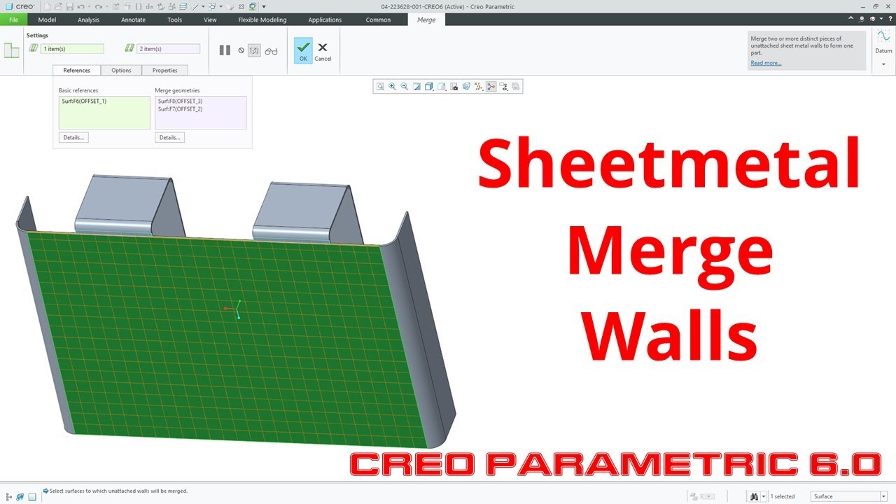
Creo Parametric 6 0 Sheetmetal Merge Walls Youtube

Dobladora De Canos Cacera Hecha X Mi With Images Metal Bending Tools Metal Working Tools Metal Fabrication Tools

Pin On 2017 Cad Tips Tricks Articles

Solidworks Sheet Metal Tutorial Electrical Enclosure Youtube Sheet Metal Solidworks Sheet Metal Art

Create Circle To Rectangle Sheet Metal Blend By Two Best Ways In Creo Parametric Youtube

Solidworks Sheet Metal Tutorial Exercise Youtube Solidworks Solidworks Tutorial Sheet Metal

Creo Parametric Sheetmetal Flattening Methods Flat Pattern Unbend And Flatten Form Youtube
Create A Flat View

Creo Sheet Metal Join For Beginners Sheet Metal Bracket 3 In Creo Parametric Youtube

E21 Creo Parametric 2 0 Sheet Metal Cylinders Youtube

Creo Sheet Metal Rip Flange Split Area On Flat Wall In Creo Parametric Youtube

Deep Drawing Sheet Metal Metal Shaping Sheet Metal Work
Https Encrypted Tbn0 Gstatic Com Images Q Tbn 3aand9gcsgropf4hikmkjd05qao3j 90nhaylgnfpuiwzhb0r7j1vrf13l Usqp Cau
Source : pinterest.com
